Site map


Site map | ||||
 |
 |
 |
 |
 |
 |
 |
 |
 |
|

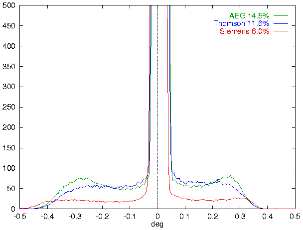
This figure shows tube tails of three different tubes operating with identic
current/voltage as measured with a 40µm slit at sample position plus
a 30µm receiving slit. All tubes were long fine focus types
(12x0.04mm2 optical focus). The AEG FK61 tube was at
4500 hours life stage, the Thomson FK61/Siemens KFLCu2K tubes were new.
KFLCu2K is a brand new ceramic type. Maximum intensities are 5500...7000 cps.
Diffractometer was an XRD7 with 175mm radius.
Learnt profile shapes include this tube tails as part of the geometry function.
This tube tails depend on
Since version 2.4.3, you should use the switch
TubeTails=...in the
*.sav file for the GEOMET run. Give a tube tails
measurement as shown above. You may use the same file formats as for the
VAL[x] entry for measurement data input.
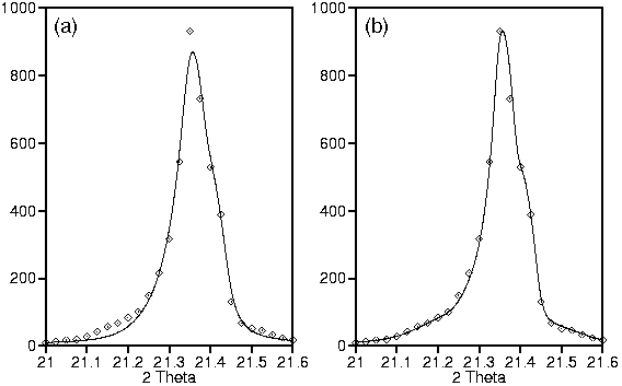
For explanation, we show the measurement of SRM 660 standard (LaB6) without (a) and with (b) tube tails correction for the used AEG tube:

We have measured the SRM 660 standard with two different tubes using identic slits. For demonstration of remaining errors, we give results using two different Cu Kα spectrae as cited from
| Cu Kα from Berger (1986) Diffractometer: XRD3000TT |
Cu Kα from Hölzer et al.
(1997) Diffractometer: XRD3000TT |
Co Kα from ibid. Diffractometer: URD6 |
||||||||||||||||||||||||||||||||||||||||||||||||||||||||
|
|
| ||||||||||||||||||||||||||||||||||||||||||||||||||||||||
Obviously, the data given by Berger (1986) are somewhat to broad compared to Hölzer et al. (1997). Data given by Hölzer et al. give comparable results for different anodes. Therefore, we recommend using the data given by Hölzer et al., which are available for Cr-, Fe-, Co- and Cu-anodes.
Using tube tails correction, one may think about using BGMN for line profile analysis (size/strain analysis).